 2025-01-15
With the rapid advancement of artificial intelligence technology, a diverse array of AI applications has permeated various aspects of professional, academic, and personal life, including chatbots, virtual anchors, and Artificial Intelligence Personal Computers (AIPC). To enhance user experience and improve responsiveness to temporal demands, there is a necessity for the development of more sophisticated large language models with an increased parameter volume.
It is noteworthy that the recently launched Llama 3.1 model boasts an impressive parameter scale of 405 billion.
The training of such a substantial model necessitates the support of ultra-large-scale intelligent computing centres. Recently, Elon Musk announced via social media that xAI has commenced training at the world's largest supercomputing facility, known as the "Super cluster," which utilizes 100,000 liquid-cooled GPUs. The interconnection of 100,000 GPU power cards requires high-speed network channels. For further details on the construction of high-performance computing networks, one may refer to resources such as "Intelligent Computing on the Internet" and a detailed analysis of Ruijie's AIGC network solution.As intelligent computing centres expand, the optical market is increasingly occupying a significant share of data centres. During the 100G era, the ratio of optical modules to networks was approximately 1:1; however, in the 400G era, this ratio has shifted to 7:3, underscoring the critical importance of optical modules within clusters. This article will focus on the failure rates of optical modules, analyze the primary causes of failure in traditional Digital Signal Processing (DSP) modules, compare failure rates utilizing LPO technology, and discuss the advantages presented by LPO modules.
Optical modules are widely recognized components within network infrastructure, essential for various applications. This prompts an inquiry into the types of optical modules that will be integrated into computing power networks.
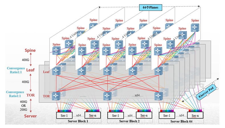
The diagram presented illustrates the current mainstream network architecture utilized in the RoCE Ethernet solution for intelligent computing centres. In this configuration, servers connect to the computing power network via a 400G high-speed network card. Additionally, a data centre switch equipped with a 51.2T switching chip establishes a three-tier architecture capable of supporting a cluster scale exceeding ten thousand cards.

The requirement for the module rate at the Intelligent Computing Centre has reached 400G, with considerations for implementing 800G interconnection in the switch interconnections. Currently, the predominant switching chip available is the 51.2T model, which utilizes 112G SerDes technology, necessitating the adoption of Q112 packaging for the corresponding optical modules on the switch side. On the network card side, the OSFP packaging format is primarily utilized, allowing for the selection of models based on the required distance during deployment.

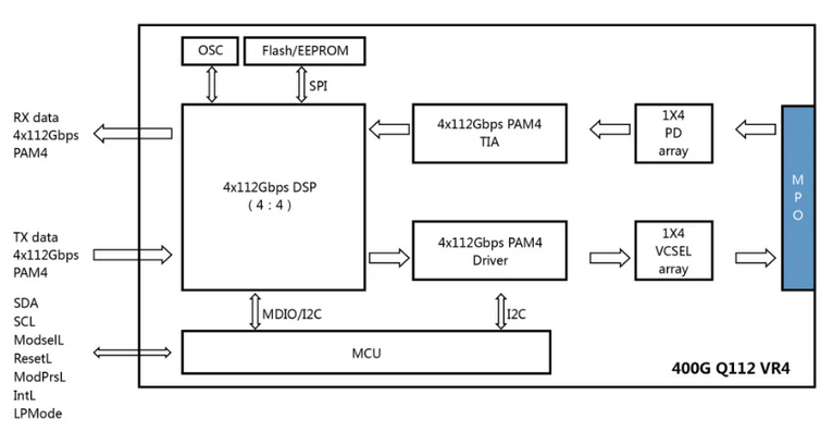
This can be elucidated by examining the 400G Q112 VR4 module as a representative example. This analysis will highlight the functional roles of the key components within DSP optical modules. It is important to note that the structural diagrams of the Short-Range (SR) and Long-Range (DR) modules exhibit fundamental similarities; however, they diverge in the electro-optical conversion methodologies employed, with the SR module utilizing Vertical-Cavity Surface-Emitting Lasers (VCSELs), while the DR module implements External Modulation Lasers (EMLs) or silicon photonics technology.

1. Exchange chips facilitate the transmission of 4*112Gbps PAM4 electrical signals into the optical module.
2. The Digital Signal Processor (DSP) chip reshapes the transmitted electrical signals before forwarding them to the driver's side.
3. The driver is responsible for transmitting the electrical signals to the laser.
4. The Vertical-Cavity Surface-Emitting Laser (VCSEL) converts these electrical signals into optical signals, which are subsequently transmitted to optical fibres.
5. Upon traversing the optical fibre, the optical signal is converted back into an electrical signal upon reaching the photodiode (PD) array of the receiving optical module.
6. The Trans impedance Amplifier (TIA) amplifies the converted electrical signals and relays them to the DSP chip.
7. Subsequently, the DSP chip reorganizes the electrical signal and sends it to the switch chip once more.
site: https://www.ruijienetworks.com/support/tech-gallery/a-brief-discussion-on-the-technical-advantages-of-the-lpo-module-in-the-aigc-computing-power-network